
The Story behind Zusie
The story behind Zusie begins in May 2008, when I went on vacation to Berlin for a few days with a friend. As is my habit, I looked for interesting technical or scientific sites to visit, and the main thing to visit was the Technische Museum. I think I spent a full day day there, to the expressed dismay of my friend, who for some reason always fails to see the beauty in old smelly circuit boards. It's a very nice museum, they had a very nice Max Planck exhibition when I was there, but the main attraction for me was without a doubt the Konrad Zuse exhibit.
Now, I am essentially a software guy. I have a master's in Engineering Physics but work on distributed database and information retrieval software for a living. I have always had a keen interest in electronics and the history of computing, and I have always shared my dwelling with a fair share of technical junk. I had some idea of who Konrad Zuse was, but I knew no details of what he had done.
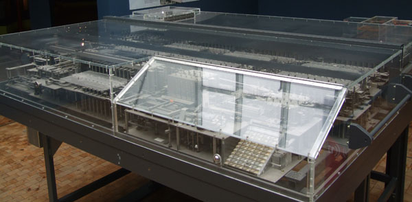
The rebuilt Zuse Z1 in Berlin.
Konrad Zuse, born 1910, invented the modern computer. A statement like that will always be controversial, but I believe it to be accurate. He was a civil engineer with many talents, but he sincerely disliked doing tedious computations. So he went along and designed and built the Z1 in 1935-1938, arguably the world's first operational binary mechanical computer, in his parent's living room in Berlin, to get out of doing manual computations. This machine is completely mechanical, and is built from thousands of metallic strips that hook into each other. But its features included a 64-by-22 bit floating-point RAM, a control unit, microcode, decimal input and output devices, paper tape program reader and an ALU with all regular floating-point operations. Implemented with METALLIC STRIPS. And with NO outside design help. The man just went along and built it! An amazing feat.
In the museum I saw the rebuild of his first machine (the original machine was destroyed in WW2), which Konrad Zuse redesigned from memory when we was over 80 years old. I was absolutely amazed. I also learned about other machines that Zuse built, in particular the Z3, the world's first general-purpose relay-based computer, completed in 1941. This was during WW2, so Zuse had absolutely no contact with any other researchers working on computers. In Great Britain and America, there were substantial collective efforts to build similar machines at this time, but Zuse, working alone, didn't just build the first functional machine, he was the first to realize that such a machine should be binary (like all computers today) rather than decimal.
The metal strips used for the Z1 proved too unreliable, so Zuse switched to electrical relays for the Z3. His father was able to find him a big bunch of discarded phone exchange relays, and with these Zuse built his historic machine. Unfortunately, it too was destroyed during WW2, but Zuse build a replica in the 1960s, and Konrad Zuse's son, Dr. Horst Zuse, has built two replicas, one in 2005 and one in 2010.
To read more about Konrad Zuse, Wikipedia is a good place to start. Several good books are listed in the references.
I got back from Berlin, and the following months I started to think about how cool it would be to build a big relay computer of my own. I didn't think it would be impossible, provided I could find the relays for it. I don't think I had ever seen or heard a relay computer (the Z3 replica is in Munich) in real life, but I could just imagine how wonderful it must sound when thousands of relays click several times a second. If you have ever heard an electromechanical telephone exchange, you know what I'm talking about.
I found 10 or so small relays laying about in a junk box, and I started to hook up simple circuits, like 1-bit adders. I also started to dooodle schematics for various relay circuits. But I knew relays were expensive - new relays can cost $10.00 or more apiece, and you would need hundreds to build a computer.
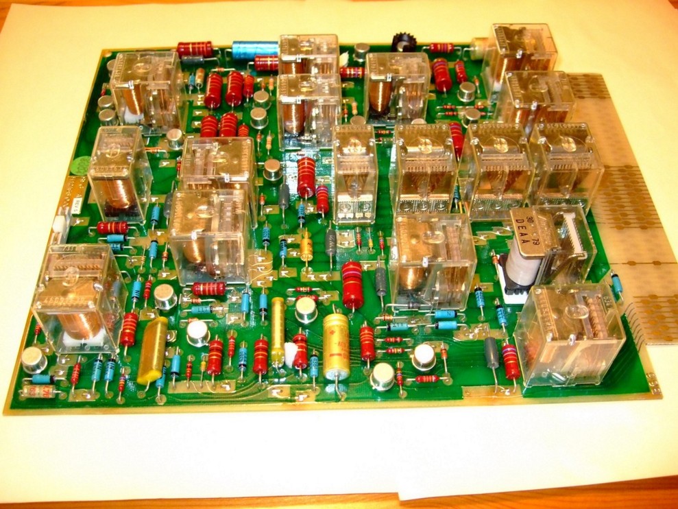
A sample board bought from Bhiab.
In January 2009, I was browsing through Bhiab Electronics' website, a Swedish dealer in surplus electronics, looking for some totally unrelated component. Looking in the section "The Junk Box" on the website, I found a couple of ancient, discrarded circuit boards that were reported to each hold about 18 relays and sold for 15 kronor (that's about $2.00)! I immediately called them up and ordered about 10 boards. That would mean 150-200 relays, enough to build me a simple ALU or something, I thought.
A few days went by, and I got the big box of boards in the mail. The boards looked to be old telephone exchange spare parts, probably from the late 70's. They were manufactured by now-defunct Standard Radio & Telefon, a classic early Swedish telecom company. The relays were absolutely perfect, 4 and 6-pole double throw ITT relays of what looked like excellent quality. Even better, all boards I received were soldered single-sided, so I thought that desoldering the relays would be doable (but very very tedious...)
I was so excited I thought to myself: This is great, more of these dirt-cheap boards and I can actually build myself a computer! However, completely overestimating the market appeal for junk relay boards, I was terrified that someone else would come along and buy the remaining boards before I could get my hands on them. I think this was on a Friday, and I decided to call Bhiab and ask if I could come by and pick up every board they had any relay on it. The owner agreed to open his warehouse for me on Sunday afternoon, two days later.
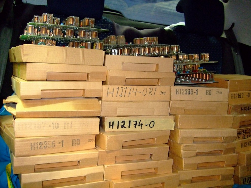
My car, absolutely packed with relay boards.
I live in Halmstad on the south west coast of Sweden, and Bhiab is in Nyköping, close to Stockholm. That's a 500 kilometer one-way trip. But that didn't stop me.. On said Sunday, I got up at 5 AM, got in my car and arrived at Bhiab sometime after lunch. Stefan, the owner, welcomed me to his store, which covered the bottom floor of a apartment house. It was absolutely packed with shelves of electronic surplus. In a room in the back were stacks upon stacks of cardboard boxes, full of the sought after boards. Now, all boards didn't include relays, so Stefan provided me with a cup of coffee and left me to go through all the boxes, picking out everything with relays on it. In the end, I had picked out about 100 boards with 8 to 25 relays on each. They filled every inch of my little car. I paid about $100 for the whole lot. I was euphoric.
I also bought a couple of really nice core memories, and some other beautiful artifacts.
I came home late in the evening, and unpacked all relay boxes onto my kitchen floor. I lived in a two room apartment at the time, and the kitchen was the only room big enough to function as a workshop. Quite the crazy arrangement. The next day I tried to desolder some relays. Desoldering one or two relays (each with 20 or so pins) with a soldering iron, I soon realized that this was a moronic undertaking. It would take me years. Not only that, but I discovered that many of the boards I'd bought were double-sided. Sigh.

My hobby workshop, in my old apartment's kitchen. Food preparation area is 2 meters behind the workbench. Not too healthy, I guess.
What to do? I got out my hot-air gun and blasted the back site of a circuit board with heat. The result was twofold. On the good side, the relays (and all other components) dislodged almost immediately and fell loose off the board. However, on the bad side, burning a 35 year old circuit board in an apartment kitchen produced nasty smoke and an undescribable smell. It smelled like what I can only describe as death mixed with poison. I ran to open every window to let some cool, fresh January air in, but it took hours before all the horrible smell was gone. I myself must have showered at least three times.
Bad idea. But still, very effective.

The desolder rig in the garage. The white hose is the fume suction arragement.
I now did what I should have done from the beginning. I called my good friend Andreas, who happens to live on a farm and have a big garage. "Hi, I've just bought 100 old circuit boards and I have just burned away half of my brain cells trying to desolder them in my kitchen. How about I haul all this stuff over to your place, like, right now??" Being the good sport that he always is, said "sure" (probably somewhat out of concern about what would happen if he said no and I started desoldering indoors again ;-)
Now followed several weeks of driving out to the garage every now and then after work and on weekends, and desoldering relays for hours on end. I got hold of a mask and Andreas and I built a suction arrangement for leading away most of the fumes. We dumped the fumes outside the building using a pump, and after an evening of work the garage's immediate neighborhood smelled utterly toxic...
I think Zusie has given me a much bigger patience with repetitive tasks... In the end, I wound up with about 1500 relays and a big box of emptied circuit boards. Even the double-sided boards were successfully desoldered. Oh, and you'll be happy to learn that I've since moved to a bigger apartment and no longer share my kitchen with a lead-ridden electronics workshop!
Desoldering the relays, identifying obviously busted ones, lovingly cleaning each one off with isopropyl alcohol, and packing them in boxes kept me busy for a few months. Eventually, I was left with 1500 or so relays, and started thinking about how to physically arrange them into a computer. I had a lot of schematics worked out already, and was eager to start building. I spent quite a long time researching different ways of construction. It's worth noting that my relays did not come in sockets, so soldering them directly would be necessary. Some means I considered were:
I eventually found a line of perfboards from Roth Elektronik, which were 100x580 mm, and exactly held 2 rows of 24 relays each. As it turned out, the 8-bit registers I had designed required 12 relays, so such a board precisely fitted 4 such registers. There was also just enough room to fit four 26-pole IDC ribbon cable headers, two on each side of the boards, so I decided that 26-pole ribbon cable (which I happened to own in bulk!) would be the interconnect for the machine.
Having decided on these build principles, I set the first long-term construction goal. First to build a board with four 8-bit registers, and then to construct an ALU to operate on these registers. In the summer of 2009, I had designed and built the register board and a rudimentary version of the ALU. This is presented in my first YouTube movie, which you can see on the right. Pay special attention to the small circuit board just above the relay boards. This is a debug board that I constructed. It consists of about 20 small relays, that take their status from the parallel port of an old PC. Using this board, I could program sequences of control signals on the PC, and then have the smaller relays drive the big 24V relay circuits' control lines. It thus operated like a fake program sequencer. This is the way that the sequence seen in the movie (read register A into ALU, perform A+1, store result in B, move B back to A) was realized.
I learned a lot about what NOT to do when I built the first board. For instance, I used regular single-stranded wires, soldered on the back side of the boards. The insulation of these wires was very prone to heat damage by the solder iron, since you're soldering so close to the plastic. It would curl up and get very ugly from the heat. I soon switched to 24AWG wire wrapping wire, which has an insulation that is almost insensitive to heat and allowed me to strip the wires very close to the solder joints without burning the insulation. This wire is very expensive though, about $1.00 per meter. But that's life.. I also learned the importance of flyback diodes, which I had thought I could ignore, since Zuse didn't use them. But neither did Zuse have an LED across every relay! What happens when you break the current through a relay, is that the coil, which is an inductor, will attempt to maintain the magnetic field by inducing a negative voltage across itself. This is called Lenz law. So what happened was that every time a relay was turned off, a voltage of -24V was placed across the LED/resistor that I had attached across most relays' coils. This sporadically burned out a lot of LEDs. So what you do to fix this is to place a backward-turned diode, known as a flyback or snubber diode, across each relay coil. This leads away the excessive back voltage before it can do any damage. Zuse made it without this, but I thought it was an OK divergence into the solid-state world..
In fact, so much was learned building these first three boards, that I decided to throw out the first board (the register board) and remake it, since it was laden with the most mistakes. Redoing things is never funny, but I'm glad I did. The new boards looks and functions much better than the old one.
Then, being quite busy at work, I worked on the machine on an off during the summer and fall of 2009. An important condition for any hobby is that you should be able to put it down when your time is needed elsewhere. You should never feel an obligation to work on your spare time projects.
In the summer of 2009, I had bought a brand new car, and wanting to take it for a good spin, I went on a road trip, once more to Germany and once more with the same friend who had accompanied me to Berlin the year before. Why Germany? Well, you see, it's pretty close to Sweden (you basically only need to pass Denmark to get there) and it is the only nation in Europe (to my knowledge) that have freeways without speed limit. How suitable when in a new car... Apart from driving, eating, drinking, sightseeing and generally relaxing, we both had our secret motives for the trip: He wanted to visit various historic sites (such as Lützen, which is of interest to Swedes due our involvment in the 30 year war in the 1600s), and of course I wanted to see as many Zuse sites as possible. I think I came out the winner of that trip.
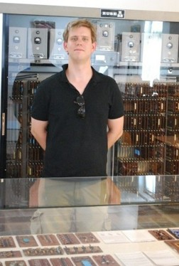
Me in front of the Z23 in the Zuse Museum
in Hünfeld, Germany, in July 2009.
I can mention Hünfeld (where Konrad Zuse lived and operated his computer business for many years nearby, and where there is today a great little museum with one floor dedicated to the man of the city), Dresden (with the Technische Sammlungen, a technical museum with some Zuse devices), and perhaps above all, the Deutsches Museum in Munich, perhaps the greatest science and technology museum I've visited. Here I finally saw the Z3 (Zuse's 1960s rebuild) and the Z4 (the original, real deal). I had been in contact with the curators before about seeing the Z3 in action, but alas they would be on vacation at this particular time. But this is a tip to you: That Z3 is operational...
I stocked up on Zuse literature during the trip, and even spent several hours in Deutsches Museum's library, digging up obscure books on relay computers. The staff there was very helpful. In Germany, you don't get all that far with English. An added bonus of the project is that, despite studying practically no German in school, I have now read enough German documents that reading new ones isn't all that difficult, and I even seem to be able to make myself vaguely understood when engaging in simple conversation with Germans. :-)
This trip was a great source of inspiration for me, and I came back with a thousand or so Zuse related photos. It must also have been around that time that I dubbed my dear project Zusie, an affectionately diminutive form of the great inventors's name. I can only hope that he would approve.
With a working register/ALU setup, now came the time to start thinking about how to retire the debug PC board and construct a proper program sequencing unit. There are basically two ways of implementing control in a computer: Hard-wired logic and microprogramming.
In hardwired control, the control lines are directly run from the machines clock logic, by means of various hardwired, fixed combinatorial networks. This provides a very pure, completely relay-based control mechanism, but also a very complex and inflexible (as in hard to change) system. Harry Porter uses this means of control in his beautiful machine.
After much consideration, I went for a microcoded approach. Microcoding is how most processors today work, and it essentially means that the sequence of control signals underlying each machine instruction is written in a type of programming language, called microcode, which is then sequenced by its own program counter. This also meant that I would be unable to implement this part of the machine using relays! Essentially, the microcode needs to be stored in a memory system, such as a RAM chip. What, No relays?!? The horror! Why on earth did I take this route?
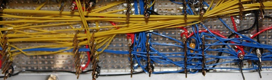
Wire wrapping closeup.
So I started work on the microcode and RAM subsystem, which would both be implemented using digital TTL logic on a common Roth perf board. I chose wire wrapping for hooking up the board. Wire wrapping is a technique that went out of fashion 25 or so years ago, where each IC circuit is placed in a socket with very long, rectangular pins. A thin wire is stretched around a pin with very high pressure about 10 times, which forms a gas-tight connection between the wire and the pin. Working on this device kept me busy for quite a few months. On the picture below, you see the workbench in the garage, when I was working on this board sometime in January 2010. This was an extremely cold winter in Sweden, with outside temperatures approaching -20 degrees centigrade. This garage is anything but insluated.. You can see the heater on the workbench. We also had about 10 to 12 kilowatts of additional heaters sprinkled across this garage, and it was still freezing cold. Eventually after a few days of this (and a few days of snowed-in roads), I grew tired of it and moved construction back to my apartment. Oh by the way, you can see my beloved HP 1631D logic analyzer on the workbench. I bought it for $150 on eBay, and it was one of the best gadgets I've ever bought.

Spring 2010 came and went with much attention focused elsewhere, but I finished the bulk of the solid-state board and also a few additional relay boards, mostly 16-bit registrers and the 16-bit incrementer and decrementer, probably the most complex board of them all in terms of meters of wire used.
To my luck, 2010 marked the 100 year anniversary of Konrad Zuse's birth. As it turned out, one of Konrad Zuse's sons, Horst Zuse, not surprisingly a professor of computer science in Berlin and a great promoter of his father's work, was building his own replica of the Z3, using modern industrial relays. He went the whole length, even building the RAM out of relays and constructing a control panel similar to that of the original Z3. This I just had to see.
I had some very pleasant email conversations with Horst Zuse, discussing his new machine that was still under construction. I assured him I would not be missing his first public demonstrations of the machine in Hünfeld in late June 2010.

Details of the Z3 replica.
So, back to Germany it was, this summer too. To my delight, one of my oldest childhood friends enthusiastically came along for the trip (not the same guy as the first two times - he has assured me that he has now seen more relays than any sane man should have to suffer through). My travel companion is an absolute car freak, so this trip took us as far as Austria, often at unmentionable velocities. But I digress.
We stayed two days at the Konrad Zuse Hotel in Hünfeld (most everything in this town seems to carry the man's name - I sincerely wish more scientists would be awarded this type of rock star status!), and was given a private demonstration of the (not quite finished) Z3 replica by Horst Zuse himself. I got answers to many questions I had about the machine's design. This was a very enjoyable and important moment in the project's history, and I wish Horst Zuse all the best in completing his machine, and I hope to see it again soon in full operation!
I also stopped by the Deutsches Museum, but alas, again it was in the middle of vacations, and no Z3 demonstration could be had. I feel I have at least given that venture my best shot...
Will there be a trip to Germany this summer (2011) too? Only time will tell. If so, I feel I may be crossing the line to fanaticism.
During the autumn of 2010, I constructed the majority of the remaining relay boards, including the one I think has the most clever design: The microcode sequencer. The microcode needs its own sequencing logic for stepping through the substeps required to complete a machine instruction. The micro sequencing cycle is basically a read-increment-store cycle, so there are inherently at least three "relay delays" involved in it. The clever thing about this device is that it parallelizes updating the microcode sequencer counter with the execution of the very machine instructions it codes for, so that the speed of the machine is not brought down by the additional burden of loading and storing microcode counter values. One thing you do not want in a relay machine are unnecessary operations, since relays are SLOW. This type of asynchronous operation was a bit challenging to implement in a stable way, and I admit I am actually a little proud of it. :-)
The other major undertaking was the writing of the machine's microcode, which meant coding the actual machine instructions that would go into the machine. It also meant developing the necessary toolchain for the machine. All of this work was carried out on an old Pention DOS laptop running the Watcom C compiler (C being my favorite language). There are three programs involved: One microcode assembler, one regular assembler for the actual programs you write, and one program which communicates with Zusie over the parallel port. All is available on the download page.
Andreas, the project's perpetual benefactor and owner of the garage which I had stolen, constantly assured me that he was in no hurry to get his garage back. However, I tried to press on. Also, I managed to involve this extremely handy and helpful man in the project in an excellent way. I needed to build a cabinet on which to mount the boards, and if there was one man who knows his way around power tools and welders, it's him.
We settled on an MDF construction for the base of the cabinet, onto which aluminum rails would be mounted to support the boards. We also designed for an aluminum control panel. Sometime late autumn 2010, we got ourselves a big board of 22 mm fiber board and started constructing the wodden cabinet. This proved a very educational experience for me. Eventually, early spring 2011, the cabinet was finished and ready for painting, something my father (a painter by trade) insisted on doing for me. If this is due to his love of his craft or doubting my own abilities in the field, I can only speculate. I settled for a medium dark grey color which quite resembles the color of old data processing equipment. The result was excellent. I had the required aluminum details made for me at a workshop, and mounted these on the MDF cabinet. I also designed a front panel for the machine, and had this manufactured onto a vinyl film which was applied to an aluminum board. Must work went into drilling, filing and fitting the front panel with a myriad of switches and other gadgets.
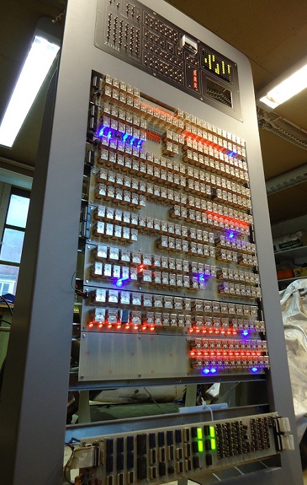
And this is where I am at right now, in June 2011. Ten boards have been built and mounted on the machine, and all interconnects and front panel devices have been wired up, and so far the machine appears to function. I am now beginning to see a glimpse of the end of this project. Stay tuned for updates

Fredrik Andersson - nablaman[at]nablaman.com
Back to Zusie home | Back to my home page